Category Archives: Colonial Marine Conversions

Colonial Marine Conversions #5: PIG

Introduction

Initially, I was going to build the missile teams as-is. When I got around to working on them, I was a little ambivalent because with all the other conversions done so far, the standard IG missile launcher just isn’t zorty enough, and not converting them in some fashion would feel like a cop-out. So, I put the missile teams on the back burner until last night.

I was watching Aliens again, and there’s a scene where Hudson is being obnoxious, and the phrase “phased plasma gun” piqued my interest. I immediately went to consult Professor Google on the subject, and after several different search queries, I finally chanced upon some online excerpts and scanned images from the Colonial Marines Technical Manual for something called a M78 PIG. This Plasma Infantry Gun, it turns out, looks exactly like a conventional shoulder-fired missile launcher with a separate power pack. Now that’s something we can do with the leftover bits in the Cadian boxed sets!


Anatomy of a PIG

According to what I’ve read, the PIG is basically the BFG 9000 of the Aliens setting. When this particular pig oinks, something explodes spectacularly. So, it’s definitely something we want to add to our little arsenal for antimateriel punch.

I didn’t want to just run a cable from the normal missile launcher to some converted power pack because, well, it’d look like a normal missile launcher attached to a power pack. This is fine for cinema, but not for miniature wargaming. People acquainted with Warhammer 40,000 generally already know what an Imperial Guard missile launcher looks like, and if we left the missile launcher as-is, people would automatically think “missile launcher” when they look at it. So, we want to change the way it looks a bit.

I decided I wanted to make it look a little bit more like a gun than a missile launcher, while still retaining the overall form factor of a tube-shaped shoulder-fired weapon. Looking through the leftover bitz, I found that the autocannon and lascannon remnants would do a nice job of changing the silhouette of the weapon, and the leftover voxcaster halves from the Sentry Gun conversions would make great power packs with a little work.

Required Parts

The photo below illustrates the parts needed for this conversion. When only a small portion of a part is required, the important piece is highlighted in red. (Save the leftover pieces! They’ll come in handy later.)


Configuration

The photos below show how all the parts listed above go together to assemble a PIG.


Plasma Gun Assembly

  1. Slice off the front section of the missile launcher right in front of where it meets the sight. The “ring” that the sight is attached to and the handgrip assembly both form a nice guiding line all around the tube to use as a cutting guide.
  2. Slice off the rear section of the missile launcher, from the very back of the shoulder rest.
  3. Carefully slice the longest barrel section off the autocannon barrel segment, leaving only the “ring” and two short tubes. Be careful doing this, as you need both pieces in usable condition.
  4. Clean up and trim the 2-tube segment of the autocannon barrel so that each tube is about 3mm long. Glue that to the front of the missile launcher body.
  5. Slice off the tube-like cap on the front of the missile launcher blast shield. Make sure the back of the cap is nice and even.
  6. Glue the blast shield cap to the front of the autocannon barrel segment attached to the missile launcher body.
  7. Slice the muzzle off the lascannon barrel. Remove the angled segment so that the muzzle is flat on both ends.
  8. Glue the lascannon muzzle segment to the back of the missile launcher body, with the grooves facing up.
  9. Glue the finished PIG to the normal missile launcher arm and set it aside to dry.

Power Pack Assembly

  1. Remove the remaining aerials from the voxcaster pack, and slice off the speaker assembly on its right side. This will leave a roughly 45 degree bevel along the upper right side of the pack, so clean and shave that area until it looks natural. Essentially, you want to make sure the bevel is nice and even along the whole edge. This forms the upper half of the power pack.
  2. Slice off the little box on the left side of the voxcaster pack, and shave the side down flat.
  3. Align the longer autocannon barrel segment with the bottom of the voxcaster pack, then trim and shave it so that it is the same width as the voxcaster pack. This will form the bottom half of the power pack.
  4. Glue the trimmed barrel segment to the bottom of the voxcaster pack, and test the power pack’s fit on a loose Cadian torso to make sure it seats properly.

Power Cable Assembly (Optional)

  1. Take 2 lengths of soft metal craft wire, one of a thinner diameter than the other. Hold them together side by side, then twist the thinner wire tightly around the thicker wire. Continue twisting until you have approximately 26mm of ribbed cable. (Note: this process is very quick if you have a pin vise handy. Simply insert both wires into the chuck, tighten it, then twist the pin vise while holding the thin wire perpendicular to the thick wire.)
  2. Snip the cable out, leaving approximately 3mm of the core wire protruding from each end.
  3. Using a drill bit of equivalent thickness to the core wire, drill one hole in the back of the PIG’s shoulder rest and another hole on the bottom right of the power pack.

Figure Assembly

  1. Assemble the figure’s base, legs, and torso only.
  2. You will need to shave off the boxlike protrusion on the back of the figure’s helmet.
  3. Glue the power pack to the figure’s back, then glue the head into place.
  4. Glue the right arm to the figure. Note that the right arm may need to be gooshed around just a little bit, as the missile launcher wasn’t designed to be used with a backpack.
  5. Glue the left arm to the figure, making sure you add a little dab of glue to the underside of the left hand’s fingers. (This will be attached to the sighting unit.)
  6. After the glue has set, bend and twist the power cable so that it fits on the PIG and its power pack nicely.
  7. Apply a dab of superglue gel (cyanoacrylate adhesive) to each hole, then insert the power cable permanently.

Consult the photos below for clarification on where to drill the holes for the power cable, and how to install it so that it sags nicely:
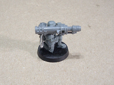
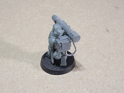

You’re done! Repeat this one more time, and you’ll have a pair of PIGs.

Colonial Marine Conversions #4: Autoloading Mortar

Introduction

This conversion actually has nothing to do with Aliens, but it uses several leftover bits from the Aliens-themed conversions, and follows the “waste as little as possible” philosophy. We’re going to use up most of the leftover autocannon bits to make a pair of autoloading mortars.


Anatomy of a Thumper

The mortar we’re going to make is called a “Thumper” because that’s the name that immediately popped into my head when I saw the finished product. Because the rear half of an Imperial Guard autocannon (left over from the last few conversions) looks too cool to waste, I decided to see what I could turn it into. Initially, I was simply going to do a snub-nosed autocannon, but because I don’t have anything to mount a snub-nosed autocannon on, that wasn’t an useful option. When I looked at the heavy weapon sprues again, I noticed the mortar parts and everything clicked.

Tube mortars seem so ghetto compared to the conversion work we’ve already done so far, so an autoloading mortar is exactly the kind of thing that goes well with the nature of the other conversions, and it’s also a nice companion to the sentry gun and missile launchers.

The two smartgun conversions use up one and a half of the heavy weapon bipods–one bipod yields two barrels and two waldo attachment points, so the only thing that comes off the second bipod is the cradle that you glue the targeter to. That leaves two usable sets of bipod legs, albeit without the cradle/yoke doohickey on top. Those cut-down bipod legs happen to be exactly the right height for this application. The grenade launcher barrels left over from the sentry gun conversion are also used in this conversion.

Required Parts

The photo below illustrates the parts needed for this conversion. When only a small portion of a part is required, the important piece is highlighted in red. (Save the leftover pieces! They’ll come in handy later.)


Configuration

The photos below show how all the parts listed above go together to assemble a Thumper.


Assembly

  1. Slice the baseplate off the mortar half where the ball socket meets the tube. Follow the angle of the ball-and-socket connection when cutting, as you will need that angle to properly seat the new mortar.
  2. Slice off the little nub near the business end of the mortar. Make sure it’s nice and even at the back.
  3. The upper back of the autocannon body has a box-shaped overhang–cut that off so that the back of the autocannon is completely flat.
  4. Slice off the little pin on the yoke that normally fits into the hole on the tripod.
  5. Glue the ammo drum to the autocannon body.
  6. Glue the grenade launcher barrel to the front of the autocannon body.
  7. After the glue sets on the parts you just attached in Steps 4-5, glue the mortar baseplate to the back of the autocannon. You want to position the baseplate so that the bottom rear of the autocannon body is sitting directly on the front “petal” of the baseplate, about half a millimeter in.
  8. After the glue on the baseplate sets, glue the whole thing to a 25mm slottabase, positioning the baseplate so that it hangs over the edge of the slottabase by a millimeter or so.
  9. Immediately apply some glue to the feet of the bipod and position it so that the bottom rear of the yoke is resting on the “pins” of the bipod legs, and the top of the bipod is aligned neatly with the yoke.
  10. Run a bead of glue across the joint where the top of the bipod and the yoke meet.
  11. Glue the mortar bipod nub to the top of the bipod, upside down, so that the 45 degree slope on the nub is as close to the autocannon yoke as possible.

You’re done! Repeat this one more time, and you’ll have a pair of Thumpers.

In the next article, we’ll build a pair of piggy-wiggies.

Colonial Marine Conversions #3: Flame Unit

Introduction

Another staple of the Aliens film is the flame unit, which is a rifle-sized weapon with an attached fuel canister, so we gotta have at least a couple. This conversion is a slightly modified version of the flamer in Stupid Bitz Tricks #5. At that time, the flamer I found in my bitz box had already been converted to use the muzzle from a Cadian flamer.

This time, we’re keeping the original Space Marine flamer’s muzzle. We’re doing this conversion now because it uses another leftover bit from the Sentry Gun conversion.

Anatomy of a Flame Unit

The Cadian box comes with a delightfully retro-looking flamer that has large backpack fuel tanks and a massive wand, which isn’t quite going to fit in with the rest of the Aliensy stuff we’re doing. So, we’re going for something closer to the movie weapon in look and feel, and we’ll be doing this by shortening and trimming down a standard Space Marine flamer. The Space Marine flamer already has a reasonably close form factor, that being a rifle-sized weapon with an attached fuel canister.

Required Parts

The photo below illustrates the parts needed for this conversion. When only a small portion of a part is required, the important piece is highlighted in red. (Save the leftover pieces! They’ll come in handy later.)


Configuration

The photos below show how all the parts listed above go together to assemble a flame unit.


Assembly

  1. Slice the muzzle off the flamer.
  2. Slice off the remaining barrel stubs on the flamer so that the muzzle will fit flush with the front handguard.
  3. Slice off the “hook” on top of the flamer.
  4. Slice off the entire grip assembly on the flamer, using the front of the flamer’s trigger guard as the guide.
  5. Glue the flamer body to the front of the grenade launcher grip on the right arm.
  6. Glue the flamer muzzle to the front of the flamer body.
  7. Carefully slice the open left hand off at the wrist, and do the same for the closed fist on the Cadian flamer left arm.
  8. Glue the open left hand to the wrist of the Cadian flamer left arm.
  9. You may have to goosh the arms around a little bit to get a nice angle on the flame unit, and you might also need to tweak the left hand a little so the flame unit sits in it nicely. When you glue the arms into place, consult the photo below to see how the arms should be positioned.


You’re done! Repeat this one more time, and you’ll have a pair of flame units.

In the next article, we’ll make a pair of autoloading mortars.

Colonial Marine Conversions #2: Smart Gun

Introduction

Another Aliens-themed item is the smart gun, which can be made easily from a couple of heavy weapon bits and a set of flamer arms. This conversion also requires one bit left over from the Sentry Gun conversion.

Incidentally, the original version of this weapon used an Imperial Guard vehicle heavy stubber, but that part makes for an expensive conversion, so I went back to the drawing board to find a way to get the same sort of weapon from cheaper and more common bits.

Anatomy of a Smart Gun

The basic idea behind the smart gun is that it’s a large and somewhat cumbersome machine gun that automatically tracks targets by means of sensors and an actuated harness system, while the actual firing is done by the operator. The significant characteristics of this weapon are, therefore, its size, the auto-tracking capability, a high rate of fire, and the fact that it’s fed by a drum magazine. We are going to incorporate those themes so that while the converted smart gun does not look exactly like the one in the movie, it will still have the correct look and feel.

Required Parts

The photo below illustrates the parts needed for this conversion. When only a small portion of a part is required, the important piece is highlighted in red. (Save the leftover pieces! They’ll come in handy later.)


Configuration

The photos below show how all the parts listed above go together to assemble a smart gun.


Assembly

  1. Shave off the details on the right side of the flamer, making sure the surface is as flat as possible. (The eagle, rivets, and tubing)
  2. Slice the flamer up so that only the parts highlighted in red remain.
  3. Glue the flamer grip section upside down to the front of the flamer.
  4. Shave the back of the flamer muzzle so that it is completely flat.
  5. Glue the flamer muzzle upside down to the front of the flamer.
  6. Slice up the bipod so that only the parts highlighted in red remain.
  7. The smartgun barrel is formed by the bipod leg–slice off the bipod foot and the leg swivel, and the barrel is the leftover section.
  8. Shave the front and back of the barrel as flat as possible, then glue it to the front of the flamer muzzle.
  9. Clean up the leg swivel so that there are no remaining traces of the leg that you sliced off in Step 6. Glue that to the bottom of the flamer, directly in front of the handgrip. This adds more visual weight to the back of the smart gun, and suggests a waldo attachment point.
  10. Glue the bipod cradle to the right side of the flamer.
  11. Glue the heavy weapon targeter to the “knob” on the bipod cradle.
  12. Slice out the ribbed autocannon barrel segment. This will be the ammunition drum–make sure the front and back are nice and flat, then glue it to the lower right side of the flamer where it meets the bipod cradle. There is a peg on the bipod cradle that will serve as a convenient guide that fits between the 2 ribs on the drum.
  13. When you glue the smart gun arms into place, consult the photo below as to where the left hand should be positioned.


You’re done! Repeat this one more time, and you’ll have a pair of smart guns.

Important note: One heavy weapon bipod yields two smart gun barrels and two waldo attachment points. So, if you do both smart gunners, you’ll actually be using one and a half bipods, not two whole bipods. Use both legs and the bipod cradle of the first bipod, then remove only the bipod cradle from the second bipod. This way, you’ll have two intact bipod leg assemblies to use in the upcoming autoloading mortar conversion.

In the next article, we’re going to make a couple of flame units.

Colonial Marine Conversions #1: Sentry Gun

Introduction

The first conversion we’re going to start with is the sentry gun, because we’ll need some of the leftover bits for later conversions.

Anatomy of a Sentry Gun

In order for a weapon system to convey its autonomous nature, it needs to look the part. So, the sentry gun conversion has 3 major components: the weapon itself, the transceiver module, and the sensor module. The transceiver module is essentially just a box with an antenna on it, and it suggests to the casual observer that the thing is remotely operated. The sensor module contains the imaging, targeting, and fire control systems, and further builds upon the autonomous impression given by the transceiver module. To make it look somewhat portable, there are two carrying handles on top of the sentry gun.

Required Parts

The photo below illustrates the parts needed for this conversion, nearly all of which come from the heavy weapon squad box. When only a small portion of a part is required, the important piece is highlighted in red. (Save the leftover pieces! They’ll come in handy later.)


Configuration

The photos below show how all the parts listed above go together to assemble a sentry gun.


Component 1: Weapon Body

  1. Lascannon: Slice the lascannon barrel and rail off completely, so that only the lascannon body segment highlighted in red remains. Shave the left side of the lascannon segment flat (just the rivets and a couple of details on the “armor” section)
  2. Heavy Bolter: Slice off everything behind the feed/ejection ports, so that only the heavy bolter segment highlighted in red remains.
  3. Test fit the heavy bolter and lascannon pieces. You may need to bevel the bottom rail on the bottom rear of the heavy bolter to a 45 degree angle to ensure a flush fit. If the test fit looks good, glue them together. Fill any gaps with Squadron putty if needed.
  4. Slice the muzzle brake from the autocannon’s barrel. Glue it to the heavy bolter’s barrel.
  5. Carefully cut the drum off the grenade launcher arm. Do this by first removing the barrel, then by slicing off everything behind the drum. Make sure you don’t damage the grip section or the hand–you will need the arm later!
  6. Shave down the top of the drum so that it is flat. Test fit the drum to the feed port on the right side of the heavy bolter segment. It should fit in snugly–if not, shave the front and rear of the drum a little more until it seats nicely into the feed port. Once the fit is just right, glue the drum into place.

Component 2: Transceiver Module

  1. Cut the bottom half and the antenna off the voxcaster backpack.
  2. Test fit the voxcaster bottom half to the right rear side of the weapon. You will need to shave off 2 button-like details from the lascannon segment to ensure a good fit.
  3. Once satisfied with the fit, glue the voxcaster bottom half to the right side of the lascannon segment.
  4. Glue the antenna to the top rear of the voxcaster half to finish off the transceiver module.

Component 3: Sensor Module

  1. Glue the lascannon power pack to the left side of the lascannon segment. The power pack is large enough to cover the entire left side of the armor “cowl”, with a slight overhang to the rear.
  2. Cut the binoculars into front and rear halves at the spot where they taper from the middle.
  3. Glue the front binocular half to the lascannon power pack to finish off the sensor module.

Finishing Touches

  1. Glue the tripod to the bottom of the sentry gun assembly.
  2. Cut the carrying handle off the autocannon drum half. Do this carefully so you can ensure a nice level fit in the next step without shortening it too much.
  3. Make sure the flat pieces at the front and back of the handle are level. If not, shave or file down the longer of the two flat pieces until the handle will sit level on a flat surface.
  4. Glue the carrying handle to the top right side of the sentry gun, across from and lined up with the other carrying handle attached to the sensor module.
  5. Glue the sentry gun to a 40mm base.

You’re done! Repeat this 2 more times, and you’ll have a full set of 3 sentry guns.

In the next article, we’ll build some smart guns.